 ***
*** 
A-Mode Echoencephalography
But first, a few words about the use of a-mode ultrasound (echoencephalography) at Bowman Gray. My training began several years before the ready availability of computed tomography in the emergency center setting. An early application of ultrasound was for rapid screening of trauma and stroke patients for intracranial mass lesions. The underlying concept was that a-mode ultrasound could be used to identify structures normally located in the midline of the brain such as the third ventricle and falx cerebri. If these were displaced to the right or left it would suggest a high likelihood of a mass lesion such as a subdural, epidural or intracranial hemorrhage. Dr. McKinney developed a training program for the technique, drawing upon the excellent resources in anatomy and audiovisual support at Bowman Gray.
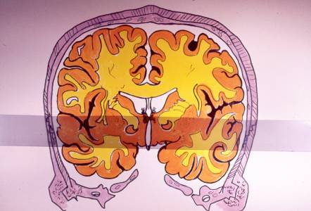
The diagram of a coronal section of the brain at the level of the third ventricle is shown below. The ultrasound beam path was illustrated by overlaying a strip of x-ray film exposed to a light gray! The corresponding a-mode ultrasound pattern is shown to the right.
***
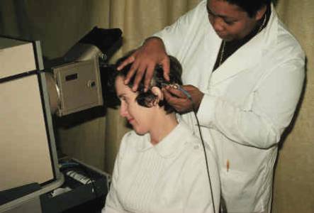
Below is a photo showing how the procedure was carried out. Performing the study is Henrietta Givens, with R.N. Patricia Nuss serving as the "patient". A scan would be obtained from the right side of the head and an a-mode image captured on polaroid film. Then the probe would be placed at the corresponding location on the left side of the head, as shown here, and a second exposure made on the same polaroid film with the spikes inverted. The midline structures would be aligned in normal patients but show displacement in patients with intracranial hemorrhage or other mass lesions.
 ***
*** 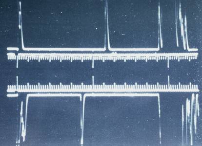
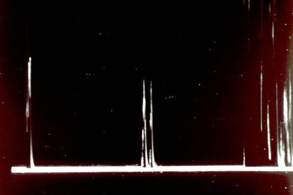
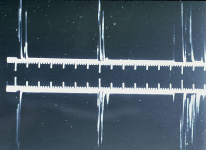
In the images above a normal study is shown at the left. Taken at the level of the third ventricle (note the two adjacent spikes at midline) there is almost perfect alignment shown in the upper (right-to-left) and lower (left-to-right) scans. The study shown at the right made just anterior to the third ventricle (note single spike at midline) shows a right-to-left midline shift.
The "a" in a-mode stands for "amplitude". When an anatomic boundary was encountered by the ultrasound beam, a vertical "spike" was created on the display with the height of the spike (its amplitude) proportional to the strength of the returning echo. Later equipment could provide "m-mode" (m for motion) or "b-mode" information (the b standing for brightness). By displaying a two-dimensional "map" of b-mode data you end up with a "b-scan", the type of image commonly used for most ultrasound images.